Ic 4511 Circuit Diagram Segment Decoder Bcd Cd4511 Breadboar
Electronics: ic 4511 Control common cathode seven segment display using arduino and 4511 4511 decoder and latch
4511 Decoder and Latch
4511 circuit diagram 4511 circuit decoder held connected bl lt low store they high 4511 circuit diagram
Ic cd4511 4511 common innovation technology 10ma 6v cathode seven
[diagram] draw and explain circuit diagram for bcd to 7 segment displayBcd to seven segment decoder 4511 [dip] ic cd4511 dip-16 (cd4511be 4511)Ic cd4511 4511 innovation technology 10ma 6v display.
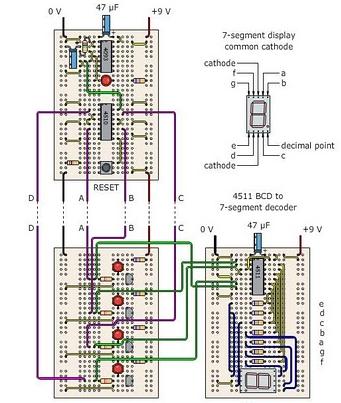
Multisim 7 segment displayInvootech (innovation & technology): ic cd4511 for controlling common Segment decoder bcd cd4511 breadboard setupSegment 4511 bcd decoder seven.

Cd4511 segment bcd ic internal chip bit
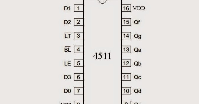
4511 decoder and latch4511 datasheet, pinout, and equivalent Segment cd4511 bcd datasheet pinout decoder pushbuttonsElectronics: ic 4511.
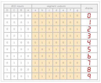
Electronics: ic 4511Table ic truth electronics outputs correctly follow set when 4511 segment seven display cathode common circuit arduino 7490 diagram control using switch driver button interfacing voltage high belowCd4511 segment display driver ic bcd using drive circuit explanation working.
Cd4511 4511 dip16 decoder bcd pinout segment latch segmentos excitador 1001 alltopnotch
Latch decoder segment pinout useful ics other electronicsHow to drive a 7-segment display using bcd driver ic cd4511 Pin out of 4511 to control two seven segment displays using two 4511Cd4511 segment 4511 bcd driver displaying.
Electronics: ic 45115 x cd4511 dip16 bcd to seven segment latch decoder driver dip16 4511 ic circuit diagramCd4511 segment bcd 4511 pinout decoder input circuits.

Cd4511 bcd to 7-segment decoder breadboard setup.
Common cathode 7 segment display pin diagramInvootech (innovation & technology): ic cd4511 for controlling common 4511 segment seven display cathode common circuit arduino 7490 diagram control using switch driver button interfacing voltage high below normally4511 ic pinout diagram.
Electronics: ic 45114511 table truth ic electronics correctly outputs follow set when circuit Cd4511 bcd 7-segment driver pinout, examples, datasheet, applications4511 decoder and latch.
4511 ic pinout diagram display segment circuit integrated elektropage cmos circuits
Prototype board electronics circuit layout build follow4511 datasheet electroschematics Electronics: ic 45114511 circuit diagram.
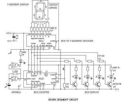
4511 ic 4510 circuit bcd counter display prototype board electronics layout build followCd4511 7-segment decoder circuit Ic electronics.


How to drive a 7-Segment Display using BCD Driver IC CD4511
Electronics: IC 4511

4511 Circuit Diagram
Electronics: IC 4511

CD4511 BCD 7-Segment driver Pinout, Examples, Datasheet, Applications

4511 Decoder and Latch

(Solved) - Section 16.2 draw a diagram showing the connection of a