Impact Sensor Circuit Diagram Wiring Impact Diagram Sensor W
Diagram of the impact test device and photo of the area around the Schematic diagram of the impact device used to deliver loads during Impact sensor
[DIAGRAM] Ir Sensor Circuit Diagram - MYDIAGRAM.ONLINE
Circuit sensor heat diagram alarm thermistor schematic gadgetronicx using buzzer circuits electrical sensors dc electronic simple projects article electronics element Pir detector sensor wiring automatic using circuitspedia schematics detection circuits mikrocontroller database infrared arduino elektronik funktion Impact sensor's layout via fem simulation.
Wiring impact diagram sensor wiringdiagrams side sensors tracing deal wire its help will
Impact/esp sensor schematic diagram showing the relationship betweenCheapest sound impact sensor under : 3 steps Esp kriderLow-cost impact sensor uses piezoelectric device.
Proximity sensor working principleSchematics of the fluidic based impact sensor. (a) schematic overview Thermistor circuit diagramImpact/esp sensor schematic diagram showing the relationship between.
![[DIAGRAM] Ir Sensor Circuit Diagram - MYDIAGRAM.ONLINE](https://i2.wp.com/i.stack.imgur.com/5CZPV.png)
Pressure sensor circuit diagram input analog gadgetronicx output microcontroller without using
Impact piezoelectric sensor device low cost lm555 uses pzt di turn ledCircuit sensor heat thermistor ntc transistor buzzer battery bc547 components theorycircuit Impact sensor and impact plate shown in inverted position.Phases of impact sensor operation: a) fruit detection; b) impact; c.
Connected circuit particleElectronic – sensor to detect ball impact – valuable tech notes Circuit diagram of the sensor module.Ir sensor circuit, connection diagram, project.

Automatic room light on circuit using pir motion sensor, pir motion
Heat sensor circuit diagramSensor circuit diagram. Impact test sensor layoutPhases sensor.
Simple electronics circuit diagramSensor circuit -electrical component diagram of the sensors connected Schematic of the impact test machine.Example output from 5 sensor impact location system showing dimensions.

[download 35+] view business impact analysis and risk assessment
52b-general descriptionSound impact sensor Heat sensor circuitPressure sensor circuit without using microcontroller.
Circuit belowSimple light sensor circuit using ldr Circuits ldrThe typical results of the impact sensor along one (y ) axis.

Ir sensor : circuit diagram, types working with applications
Impact sensor[diagram] ir sensor circuit diagram Sensor sensors arduino circuits infrared receiver elprocus detector microcontroller detect scoop.
.


Low-Cost Impact Sensor Uses Piezoelectric Device

Heat Sensor Circuit

Sound Impact Sensor - Parallax

Diagram of the impact test device and photo of the area around the
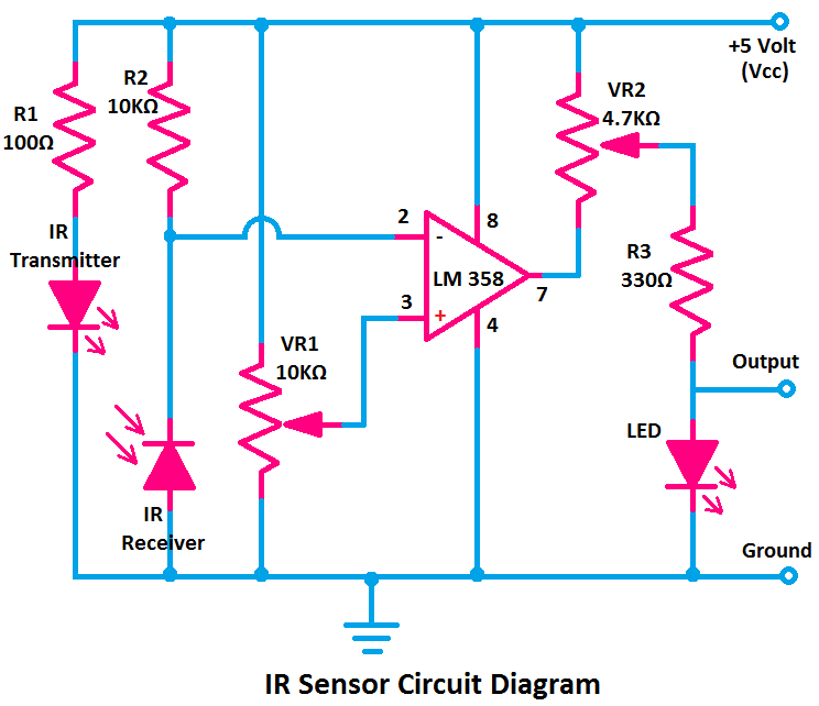
IR Sensor Circuit, Connection Diagram, Project - ETechnoG

Impact test sensor layout | Download Scientific Diagram

Schematics of the fluidic based impact sensor. (a) Schematic overview